1. The Shelby GT-350R
* Watch the completed car in action here:
Video
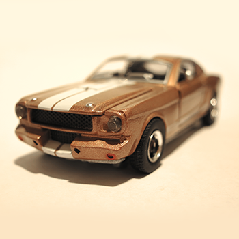
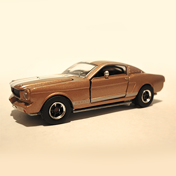
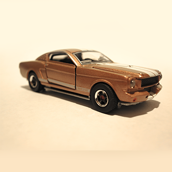
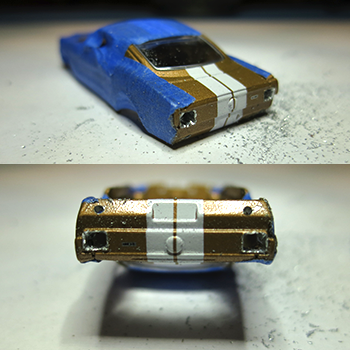
This is the stock car.
The head lights are there already, so it was a time saver.
The front signal and fog lights already has impressions in them, so drilling was a breeze also.
The only hard part was drilling the tail lights and recreating it.
This car already has opening hood and doors, so I'll have to hide the wires underneath the engine bay and seats.
I'll be mounting the door switches behind the back seat and the top switch under the rear window.
The first thing you should do is drill the mushroom rivet heads underneath the car to seperate the chasis from the base.
I won't be showing you this as there is already a few videos on YouTube.
Once they are seperated. Inspect the car's design carefully and decide where you'll be installing all the components. Every car is different, so you have to be creative here.
You must install and glue all the switches and lights before wiring.
You must also make sure you have a place to hide your battery and the ONE64LED PCB.
Cut anything that you don't need to make room for them.
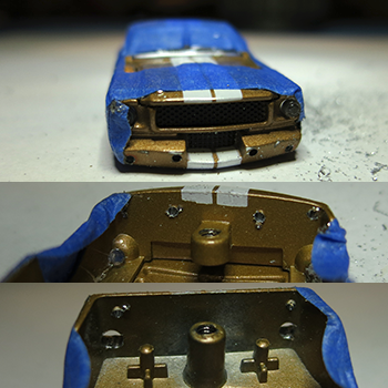
2. Drilling the Holes
Drilling holes for the tail lights, backup lights, fog lights and front signal lights require patients.
Make sure you tape the car, so it doesn't scratch, if you are not planning to repaint the car.
3.
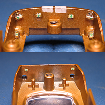
LEDs Glued
All the LEDs are glued first glued into place.
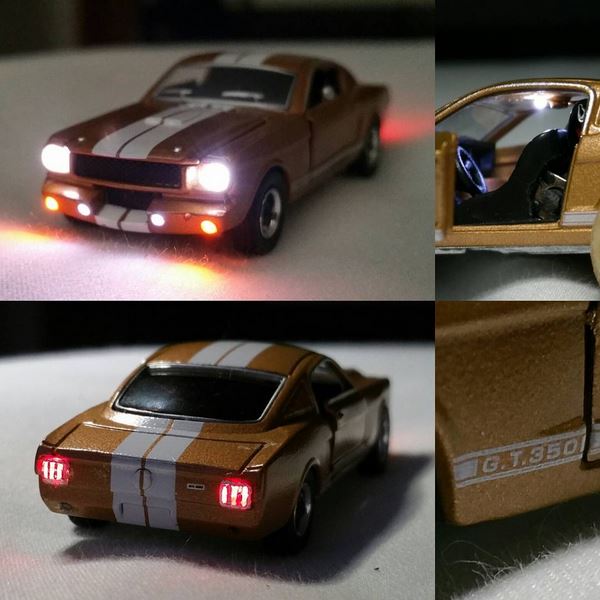
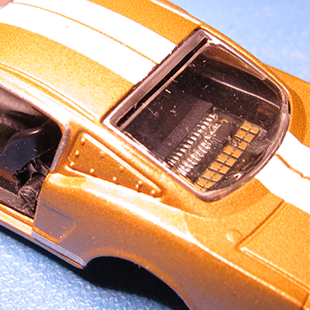
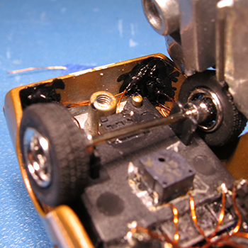
The top left picture is of the inside front end. It has the Orange signals, White fog lights in the middle and White head lights.
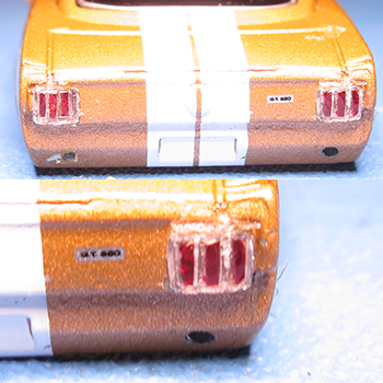
The bottom left picture is of the inside rear end.
The rear has the White backup lights in the middle.
The break lights are not installed yet. I'll have create the tail lights from the outside first. Then glue the LEDs in later.
The rear end contains the drilled backup lights and tail lights.
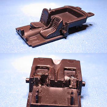
5. Left and Right Buttons
The buttons are glued behind the seats.
The bottom of the floor board and part of the seat's rear had to be cut to fit the buttons.
They are stratigectly mounted, so the doors can press on them, when pushing on the doors.
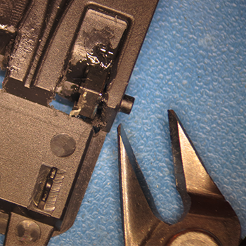
Once you have the switches glued to where you want.
Trim or cut the switches to the length that works for you.
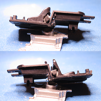
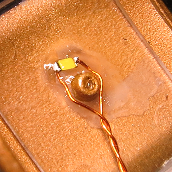
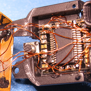
6. Switches & ONE64LED PCB
The switches are installed behind the seats at the bottom corner. Same for the passenger side.
The doors will press on it when pushed in.
Trim the switches, so the doors look closed, but has a some sort of travel to actuate the switches.
The PCB is glued into place in the rear. There is no wiring yet. I'm just fitting it in.
7.
Tail lights
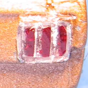
I wiped the inside of the drilled tail lights with glue accelerator, so when I apply glue. It'll instantly dry.
Then I slowly fill the hole up with glue, builing up the glue until I had enough to shape the tailights to my liking.
Once it has three rectangular shapes,
I paint the tailights with red clear paint.
Later, I'll be painting silver around the trim to resemble the chrome plated trims.
8.
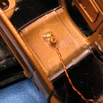
Interior Light
I then glue the interior light to the ceiling, routing the wires along the celing and then down the side.
Basically hiding it.
9. Lights & Paint Masking
After gluing the LEDs to the inside of all the light openings, solder the wires to the LED and make sure they are routed the way you want it.
Paint the whole LED on the inside of the chasis, so no light leakage can shine through inside the car.
You'll have to touch up later as you power it up. You will probably miss a few spots.
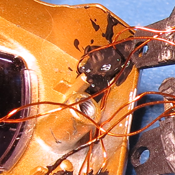
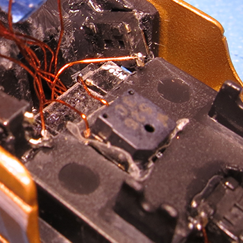
10.
PCB and Top Switch
The PCB is mounted and glued.
The TOP switch is also glued to the chasis. This time, I chose to glue it to the rear due to the car having doors that open. And I still wanted to show off the interior. It was a better choice to put the top switch in the back.
Pressing the back window down will actuate the top switch.
Trim what ever is holding the back window up, so it has a range of travel to actuate the switch. You might also need to trim the switch down so the window and switch meets halfway for a perfect springy feel to the window.
Trim down the switch enough, so the back window is still forced up when not pressed.
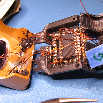
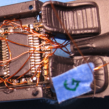
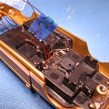
At this point. I soldered all the back lights to the PCB as i'll be closing the interior onto the top chasis.
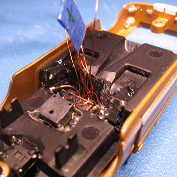
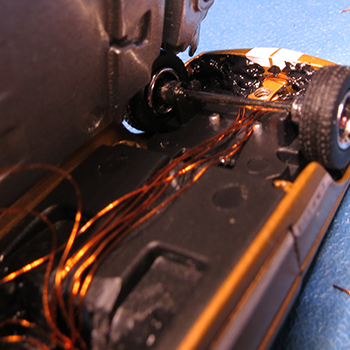
In the third picture below, I soldered each wire to the PCB that I'll be using for the the front and route them through the gap
between the chairs. The fourth picture shows the wires comming through the bottom side with labels on them.
This is because, when I close the interior, I won't be able to access the PCB anymore.
Just make sure you label each wire as to what it is. Notice the "G". That is for ground (-).
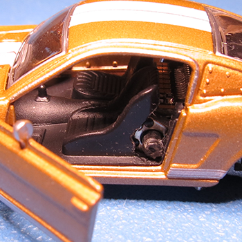
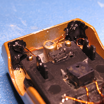
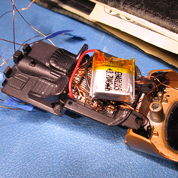
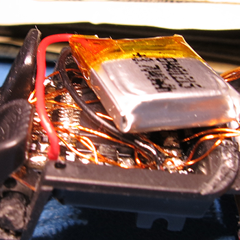
11.
Battery and Speaker Placement
I've decided to place the battery on top of the PCB, which is behind the back seat. Then I soldered the positive (RED +) and the negative (BLACK -) wires to the PCB. Remember to solder an extra wire for the (+) and (-) wires from the battery to the other side also. This will be soldered onto the charge connector on the base.
Once the battery is soldered on. You can actually press the top button and see whatever lights you already installed working.
In the third picture. I mounted the speaker right underneatch the PCB on the bottom side of the interior piece. The fourth picture give you a closer look. It sits perfectly, as it the base plate will almost touch it when closed.
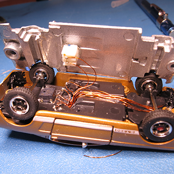
12.
Front Head Lights, Wheels and Base
Select each wire that sticks out of the gap and read what it's labeled and solder it to the correct LEDs in the front.
Route the wire so it does not stick out of the rear wells. You don't want them to show.
Remember to cover the whole LED with dark paint also to mask the light leakage.
13. Charging Connector
Now that everything is soldered. Press the top, left and right buttons accordingly to see if it works.
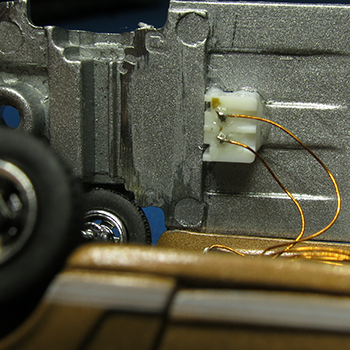
The charging connector will go on the base facing down. Just drill a pilot hole and then use a drill bit the width of the connector to drill through it.
Once drilled, you can just file all four corners and keep inserting the connector to make sure it fits snuggly and that you can still plug the female connector to it. Once satified, you can glue the connector flush to the base. Trim the two leads sticking out if it gets in the way. You don't need it that long. Just make sure you can still solder to them.
Make sure you plug the female connector in and double check the positive and negative before soldering the battery to it.
If all LEDs are soldered correctly and is working. Solder the last two (+) and (-) wires to the male connector on the base.
Remember to put an electrical tape over the two pins before closing the chasis and base together. IT IS VERY IMPORTANT, cause you don't want them to short together.
14. Screw It All Back
Now that everything works.
And you have put a piece of electrical tape over the male connector's two pins.
Screw it all back and enjoy.
Please upload videos of what you have created and email us. As we are interested in seeing what everyone has created also.